
ANALYSIS OF WALL STRUCTURAL RESPONSE AND STABILITY IN DIFFERENT ANCHORED POSITIONS
Idrees Saad1, Mohamad Gabar2 , Rabh Salem3 , Amera Abdel4 , Abdullah Othman4 Abdullah Idress4
Research, Consultancy &Training Center, Tobruk University, Tobruk, Libya
2,3 Department of Civil Engineering, Tobruk University, Tobruk, Libya
4 Department of Civil Engineering, Tobruk University, Tobruk, Libya
E-mail: mohamadg980@tu.edu.ly
HNSJ, 2024, 5(5); https://doi.org/10.53796/hnsj55/21
Published at 01/05/2024 Accepted at 05/04/2024
Abstract
Deep excavations are usually performed near high-rise buildings, and tiebacks are used to provide the lateral resisting force for many excavation support systems and anchored retaining walls. Therefore, the engineering challenges lie in safely execution the excavation stages and the security of surrounding buildings. Libya, in particular, has numerous old buildings that require safety and stability measures during excavation operations, particularly in urban areas. This research aims to investigate the structural response of anchored walls through parametric studies under varying conditions. The study was conducted using the PLAXIS 2D version 8.2 finite element program, employing 15-noded triangular elements. Thirty-two cases were carried out to investigate the effects of different anchor positions (P) and various soil on parameters such as horizontal wall displacement, wall bending moment, anchor force, and soil stresses. The excavation is supported by concrete diaphragm walls utilizing tiebacks in the form of pre-stressed ground anchors (Anchor node to node and Fixed anchor). An overall analysis of the results reveals a predictable behavior of the walls, with reduced displacement and bending moment for improved soil and wall characteristics.
Key Words: Structural response; Stability structure; Walls with anchors; Profound excavations
عنوان البحث
تحليل الاستجابة الهيكلية للجدار وثباته في المواقع الراسية المختلفة
HNSJ, 2024, 5(5); https://doi.org/10.53796/hnsj55/21
تاريخ النشر: 01/05/2024م تاريخ القبول: 15/04/2024م
المستخلص
الحفريات العميقة عادةً ما تتم بالقرب من المباني الشاهقة، وتستخدم عملية الربط على الجدار لتوفير القوة المقاومة الجانبية للعديد من أنظمة دعم الحفر والجدران الساندة المربوطة. وبالتالي، تكمن التحديات الهندسية في تنفيذ مراحل الحفر بأمان وضمان أمن المباني المحيطة. خاصةً في ليبيا، حيث توجد العديد من المباني القديمة التي تحتاج إلى تدابير أمان واستقرار أثناء عمليات الحفر، لا سيما في المناطق الحضرية. يهدف هذا البحث إلى دراسة استجابة الجدران المربوطة من خلال الدراسات الأساسية تحت ظروف متغيرة. لذا تم إجراء الدراسة باستخدام برنامج العنصر المحدد ثنائي الأبعادPLAXIS 2D الإصدار 8.2، وذلك باستخدام عناصر مثلثية مكونة من 15 نقطة. كذلك إجراء اثنتين وثلاثين حالة لدراسة تأثير مواقع الربط المختلفة (P) على الجدار ومختلف معاملات التربة على معاملات مثل التشوه الأفقي للجدار, وعزم الانحناء للجدار، وقوة الربط, وضغوط التربة على الجدار. يكشف التحليل الشامل للنتائج عن سلوك قابل للتنبؤ للجدران، مع تقليل التشوه وعزم الانحناء لتحسين خصائص التربة والجدار.
- INTRODUCTION:
Retaining walls serve various purposes, such as agricultural terraces, houses, railroads, and highways. According to California Dot (2004),there are different types of retaining walls, including gravity, semi-gravity, cantilevered, and anchored. Anchored walls are particularly important because they prevent the soil beneath them from sliding downward. An anchored wall is designed to withstand the lateral stresses present behind it. These walls have a limited height to withstand lateral stresses. Anchors are used to hold walls and resist significant lateral forces when reasonably high walls are required.
During the design of retaining walls, factors such as lateral earth pressure, surcharge load, hydrostatic pressure, and seismic loads must be considered to ensure the walls can withstand external forces. When there is a desired change in ground elevation that exceeds the angle of repose of the soil, an anchored wall is constructed to resist the lateral pressure from the soil. Chehade et al. (2008) [1] observed a significant variation in the maximum bending moment in the structure after excavation, especially for rigid structures. Mohamad Gabar 2022 [2] demonstrated how the structural behavior of the wall is influenced by soil properties, anchor characteristics, and wall design. Abhijit Debnath & Sujit Kumar Pal 2023 [3] found that the optimal placement of anchors in double wall is between 0.25H and 0.5H, where H represents the wall height.
Mauricio Ehrlich & Rafael Crequeira Silva 2015 [4] discovered that slope stability is negatively affected by low shear resistance and inclination of the wall, which varied between 58° and 80° from the horizontal along the excavation length. Nikiforova 2005 [5] highlighted how research findings from the Scientific-Research Institute of Foundations and Underground Structures’ have helped reduce geotechnical risks in the construction of deep trench projects in densely populated areas of Moscow.
The sheet pile wall technique, as described by Dinakar 2014 [6], effectively reduces ground disturbances caused by excavation. Parametric research also indicates that safe excavation to greater depths can be achieved with reduced wall distortion and bending moments. According to Abdelrahman E. Aboelela et al., 2022 [7], excavation-related de-stressing affects the Modulus of Subgrade Reaction Value ks. When a wall exceeds a height of 6 meters or supports significant loads from a structure, anchors are incorporated, as stated by the National Cooperative Highway Research 2008 [8]. Mohamad Gabar and Ömer Bilgin 2016 [9] investigated how wall behavior is influenced by factors such as bedrock slope, soil conditions beneath the wall, and various wall heights.
Dawkins, William P. in 2001 [10] examined the effects of wall friction, surcharge loads, and moment reduction curves for anchored sheet-pile walls. The influence of subsurface soil characteristics on floodwall behavior was investigated by Ömer Bilgin in 2009 [11]. Studied the influence of subsurface soil characteristics on floodwall behavor. Anchors are used to minimize wall displacements and prevent overturning. The development of cracks in the wall may be attributed to lateral earth pressures and/or water pressures exerting additional pressure.
The research presented in this study enhances knowledge and understanding of the behavior of different soil types (clay, sand, loam, and fill) behind and below the wall, as well as the impact of various wall characteristics, anchor positions, anchor lengths, and anchor types on wall behavior.
1.1 Objective of this Research:
The structural design of retaining walls today takes into account the soils in the front and back of the anchored wall. Previous research has shown that the thickness and presence of a soft soil layer beneath the wall can affect its deformations (Bilgin, 2009). However, the impact of the soils beneath the anchored wall has not been extensively studied in earlier investigations. This study aims to examine how different anchor positions influence the behavior of the wall by analyzing the effects on stresses, bending moments, and anchor forces. Additionally, the study investigates how the use of different anchor types affects how the wall’s behavior in various scenarios.
1.2 Scope and Parametric Study:
The main goal of this research is to use parametric studies under various scenarios to examine the structural reaction of anchored walls. The excavation is 80m wide and 20m deep, 12m long concrete diaphragm walls of 0.35m thickness are used to retain the surrounding soil. Two rows of ground anchors are used at each wall to support the walls. The upper anchor has a total length of 14.5m and the lower anchor is 10m long and is installed at an angle of 45° for both as presented in figure 1.
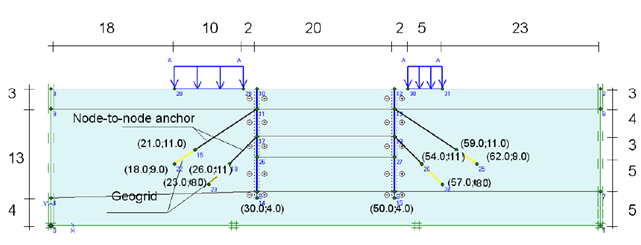
Figure (1) Geometry Model of the Situation of Dry Excavation at Depth 8m (By Author)
Different anchor points (P) (P = 16 meters, 16.5 meters, 17 meters, and 18 meters) from the loam layer utilizing various features as indicated in (Table 1, Diaphragm 2, Table 3, and Table 4) are the circumstances.
Not all practical combinations take into account all the parameters and ranges. Only specific combinations of other parameters are explored with some parameters to examine their effects. Utilizing widely available general-purpose 2-D finite element software for geotechnical engineering applications, parametric analyses were carried out through numerical modeling and analysis. In the structural study performed by PLAXIS, the deformations, moments, shear forces, and soil stresses of the walls were examined.
- NUMERICAL MODEL:
The main goal of the parametric analysis is to understand how the wall’s surroundings affect the behavior of the wall’s displacement, soil stresses, anchor force, and bending moment. The PLAXIS 2D version 8.2 finite element program which uses 15-noded triangular elements, was used to carry out the investigation. The effects of various anchor positions (P) employing various soil types, such as horizontal wall displacement, wall bending moment, anchor force, and soil stresses, were studied in thirty-two experiments. The following is a presentation and discussion of numerical analyses and outcomes.
2.1 EFFECT OF DIFFERENT ANCHOR LOCATIONS (P):
To examine the impact of various anchor locations (P) on the behavior of the wall, a parametric study was conducted. Using the previously indicated soil parameters, horizontal wall displacement, wall bending moment, wall anchor forces, and soil stresses, the anchor positions, p, were 16 m, 16.5 m, 17 m, and 18 m. Each model’s width was likewise modified by the anchor placements illustrated in Figures 2(a) and (b).
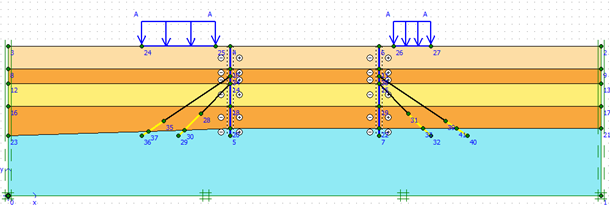
Figure (2a) Geometry Model of the Situation of anchor positions (P = 16m)
(By Author)
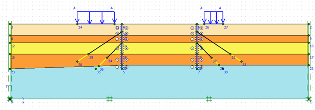
Figure (2b) Geometry Model of the Situation of Anchor Positions (P = 18m) (By Author)
Table (1) Different Soil Characteristics (By Author)
| Soil Types 1 | Soil Types 2 | |
| Case 1 | Fill | Fill |
| Clay 1 | Sand 1 | |
| Sand 1 | Clay 1 | |
| Clay 1 | Sand 1 | |
| Loam | Loam | |
| Case 2 | Fill | Fill |
| Clay 2 | Sand 2 | |
| Sand 2 | Clay 2 | |
| Clay 2 | Sand 2 | |
| Loam | Loam | |
| Case 3 | Fill | Fill |
| Clay 3 | Sand 3 | |
| Sand 3 | Clay 3 | |
| Clay 3 | Sand 3 | |
| Loam | Loam | |
| Case 4 | Fill | Fill |
| Clay 4 | Sand 4 | |
| Sand 4 | Clay 4 | |
| Clay 4 | Sand 4 | |
| Loam | Loam | |
| Case 5 | Fill | Fill |
| Clay 5 | Sand 5 | |
| Sand 5 | Clay 5 | |
| Clay 5 | Sand 5 | |
| Loam | Loam |
Table (2) Different Wall Properties (By Author)
| Parameter | Name | Value | Unit | |
| Type of behavior | Material type | Elastic *10^6 | – | |
| Diapharm1 | Diapharm2 | |||
| Axial stiffness | EA | 7.5 | 12 | kn/m |
| Flexural rigidity | EI | 1 | 0.12 | kn.m²/m |
| Equivalent thickness | D | 1.265 | 0.346 | M |
| Weight | W | 10 | 8.3 | kn/m/m |
| Poisson’s ratio | Ν | 0 | 0.15 | – |
Table (3)
Properties of the Anchor rod (Node to Node) (By Author)
| Parameter | Name | Value | Unit |
| Type of behavior | Material type | Elastic | – |
| Normal stiffness | EA | 2E5 | Kn |
| Spacing out of a plane | Ls | 2.5 | M |
| Maximum force | Fmax, comp | 1E15 | Kn |
| Fmax, tens | 1E15 | Kn |
Table (4) Property of the grout body (Geogrid) (By Author)
| Parameter | Name | Value | Unit |
| Type of behavior | Material type | Elastic | – |
| Normal stiffness | EA | 1E5 | Kn/m |
3. RESULT AND DISCUSSION:
The PLAXIS program was utilized in this study to simulate and analyze anchored walls, also known as tieback walls, under different conditions. The subsequent section outlines the findings of the analysis.
3.1 DIFFERENT ANCHOR POSITIONS’ EFFECTS (P)
This situation was created to study the impact of various anchor positions (P) on the behavior of the wall utilizing various soil types, including horizontal wall displacement, wall bending moment, anchor pressures, and soil stresses. The horizontal wall displacements, wall bending moment, anchor forces, and soil stresses on the wall are depicted in Figures 1 to 11 using PLAXIS figures and charts.
The analysis’s findings for the different soil types used in Table 1 analysis of horizontal wall displacement, wall bending moment, anchor forces, and soil stresses are presented in Tables 5 through 8, displayed in Figures 1 through 11, and described below.
Soil Stresses: As indicated in Figure (8), it is evident that there is a noticeable increase in soil stresses behind the wall when different soil types are employed (soil type 2 in all cases). However, when soil type 1 is used in cases 1 and 2 at P (16 to 18 m), the soil stresses decrease, whereas in cases 3 and 4, using soil type 1 at P (16 to 18 m) leads to an increase in soil stresses.
Horizontal Displacement: Regarding horizontal displacement, Figure 9 demonstrates that the wall experiences a similar behavior when different anchor positions are utilized in different soil types . However, the effect of horizontal displacement on the wall is reduced when an anchor is employed at 17m and 18m using soil type 2 in all scenarios. of the wall induced by utilizing different anchor positions in different soil types has a similar behavior as illustrated in Figure (9), but the effect of horizontal displacement on the wall is reduced when using an anchor at 17m & 18m by soil type2 for all situations.
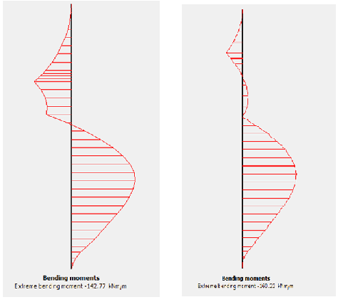
Wall Bending Moment & Anchor Force: As depicted in Figures (10 & 11), the wall bending moment and anchor force exhibit comparable behavior. Moreover, when using all soil types are employed at 16m, the anchor force and bending moment have minimal impact on the wall.
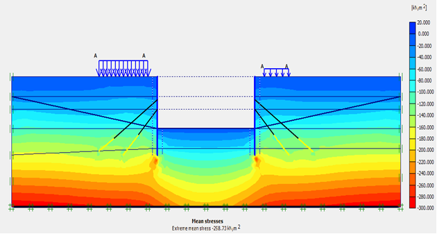
Figure (1) Soil Stresses at (P=16.5m), (By Author)
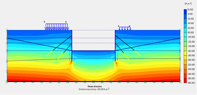
Figure (2) Soil Stresses at (P=18m), (By Author)
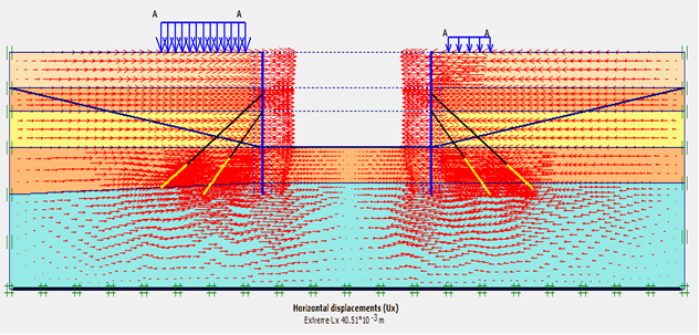
Figure (3) Horizontal Wall Displacement at (P=16.5m), (By Author)
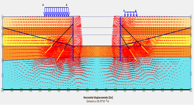
Figure (4) Horizontal Wall Displacement at (P=18m), (By Author)
(P = 16.5m) (P = 18m)
Figure (5) Wall Bending Moment at (P= 16.5m &18m), (By Author)
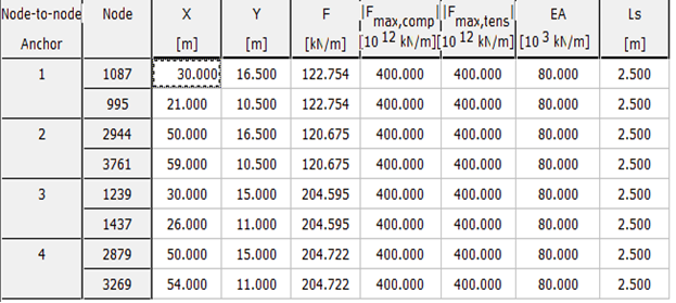
Figure (6) Anchor Forces at (P= 16.5m), (By Author)
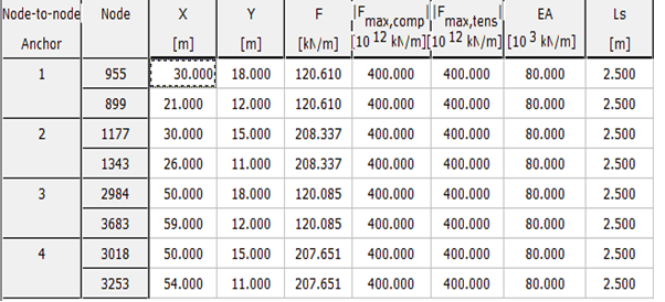
Figure (7) Anchor Forces at (P= 18m), (By Author)
Table (5) Soil Stresses for Varying Anchor Positions (P) (By Author)
| Soil Stresses [kn/m2] | ||||||||
| P18 / Type 2 | P17 / Type 2 | P16.5 / Type2 | P16 / Type2 | P18 / Type 1 | P17 / Type 1 | P16.5 / Type1 | P16 / Type1 | |
| -302.92 | -302.94 | -302.9 | -302.94 | -258.5 | -258.62 | -258.73 | -258.74 | 1 |
| -301.86 | -301.73 | -301.69 | -301.64 | -258.52 | -258.68 | -258.88 | -258.88 | 2 |
| -303.83 | -303.76 | -303.68 | -303.62 | -299.75 | -299.05 | -299.8 | -299.86 | 3 |
| -301.65 | -301.64 | -301.63 | -309.32 | -341.46 | -299.08 | -314.76 | -378.68 | 4 |
Table (6) Horizontal Wall Displacement for Varying Anchor Positions (P) (By Author)
| Horizontal Displacement [m] | ||||||||
| P18 / Type 2 | P17 / Type 2 | P16.5 / Type2 | P16 / Type2 | P18 / Type 1 | P17 / Type 1 | P16.5 / Type1 | P16 / Type1 | |
| 3.42E-02 | 3.37E-02 | 3.33E-02 | 3.29E-02 | 3.97E-02 | 3.91E-02 | 4.05E-02 | 4.19E-02 | 1 |
| 4.19E-02 | 4.85E-02 | 5.46E-02 | 5.48E-02 | 8.49E-02 | 7.40E-02 | 7.67E-02 | 7.39E-02 | 2 |
| 2.79E-02 | 2.77E-02 | 2.74E-02 | 2.71E-02 | 3.67E-02 | 3.59E-02 | 3.58E-02 | 3.62E-02 | 3 |
| 7.83E-02 | 1.36E-03 | 9.26E-02 | 9.48E-02 | 1.11E-01 | 1.08E-01 | 1.07E-01 | 1.04E-01 | 4 |
Table (7) Wall Bending Moment for Varying Anchor Positions (P) (By Author)
| Wall Bending Moment [kn.m/m] | ||||||||
| P18 / Type 2 | P17 / Type 2 | P16.5 / Type2 | P16 / Type2 | P18 / Type 1 | P17 / Type 1 | P16.5 / Type1 | P16 / Type1 | |
| -164.32 | -150.85 | -143.81 | -136.79 | -160.23 | -150.29 | -142.77 | -139.22 | 1 |
| -194.26 | -181.18 | -173.82 | -158.71 | -288.23 | -291.44 | -279.92 | -273.18 | 2 |
| -139.2 | -126.77 | -120.05 | -113.7 | -145.54 | -134.34 | -121.77 | -124.27 | 3 |
| -210.85 | -192.97 | -178.55 | -165.52 | -267.77 | -240.17 | -224.52 | -210.64 | 4 |
Table (8) Wall Anchor Force for Varying Anchor Positions (P) (By Author)
| Wall Anchor Force [kn/m] | ||||||||
| P18 / Type 2 | P17 / Type 2 | P16.5 / Type2 | P16 / Type2 | P18 / Type 1 | P17 / Type 1 | P16.5 / Type1 | P16 / Type1 | |
| 216.453 | 214.014 | 214.007 | 117.623 | 207.651 | 205.228 | 204.722 | 121.263 | 1 |
| 192.757 | 192.083 | 193.226 | 123.375 | 238.48 | 231.349 | 227.329 | 163.436 | 2 |
| 214.364 | 212.396 | 211.764 | 113.582 | 210.782 | 208.592 | 205.849 | 108.49 | 3 |
| 222.866 | 211.926 | 209.353 | 122.212 | 225.909 | 214.258 | 212.012 | 135.594 | 4 |
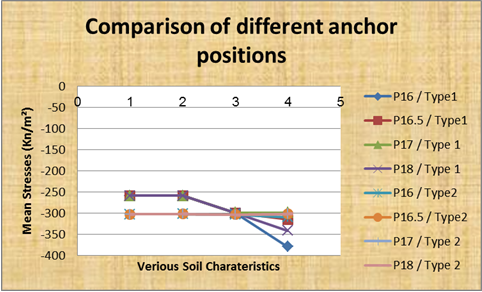
Figure (8) Soil Stresses (kn/m2) at Varying Anchor Positions (P) (By Author)
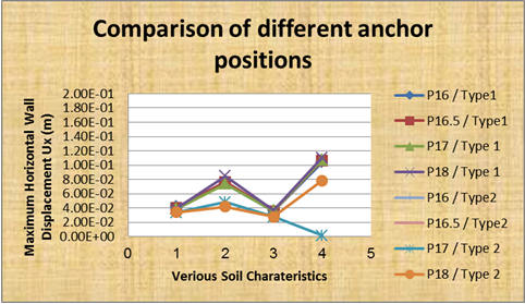
Figure (9) Horizontal Wall Displacement Ux (m) at Varying Anchor Positions (P) (By Author)
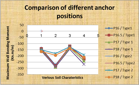
Figure (10) Wall Bending Moment (kn.m/m) at Varying Anchor Positions (P) (By Author)
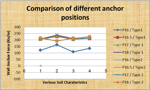
Figure (11) Wall Anchor Force (kn/m) at Varying Anchor Positions (P) (By Author)
4. CONCLUSIONS:
- The overall analysis of the results indicates that the wall behavior can be predicted with reduced displacement and bending moment when the soil and wall features are improved.
- Among the diiferent anchor positions studied, anchor positions at 16 and 18 meters using soil type 1 (cases 1 and 2) yielded the most favorable outcomes in terms of horizontal displacement, bending moment, and anchor force.
- On the other hand, anchor positions at 16 and 18 meters employing soil type 2 (case 3 and 4) generally resulted in the poorest performance in terms of anchor force, bending moment, and horizontal displacement.
- This study showcased the effectiveness of Plaxis2D and its sensitivity to even small changes in data. A significant amount of data tables were generated for various combinations.
5. REFERENCES:
- F. H. Chehade’, W. Chehade’, H. Mroueh, & L Shahrour.” Numerical Finite Element Analysis of the Behavior of Structure Near to Deep Excavations in Urban Area.” International Review of Mechanical Engineering (l.RE.M.E.), Vol. 2, No. 2 March 2008.
- Mohamad Gabar, Idress Saad, and Rabh Salem.”Depth Wall and the Stability of Anchored Retaining Walls.” Libyan Journal id Engineering Science and Technology (LJEST), Vol.2, No.2, 2022.
- Abhijit Debnath & Sujit Kumar Pal. “A numerical Analysis on Anchored Sheet Pile Wall Subjected to Surcharge Strip Loading.” Journal of Engineering Research, doi. Org/10.1016/ j.jer.2023.100088.
- Mauricio Ehrlich & Rafael Crequeira Silva. “Behavior of 31m High Excavation Supported by Anchoring and Nailing in residual Soil of Gneiss.”Engineering Geology, Vol.191,29 May 2015, Page 48-60, doi.org/10.1016/j.enggeo.2015.01.028.
- N. S. Nikiforova.” Reduction of Geotechnical Risk for Deep Excavations in Urban Settings.’ Soil Mechanics and Foundation Engineering,( Osnovaniya, Fundamenty, Russian) Vol. 42, No. 5, 2005
- Dinakar K N. ” Behaviour of Tie Back Sheet Pile Wall for Deep Excavation using Plaxis.” International Journal of Research in Engineering and Technology. 03(18):97—103, DOI:10.15623/ijret.2014.0318016.
- Ching, F. D., Faia., R., S., & Winkel, P. Building Codes Illustrated: A Guide to Understanding the 2006 International Building Code (2nd ed.). New York, NY: Wiley; 2006.
- National Cooperative Highway Research (NCHR). Seismic analysis and design of retaining walls, buried structures, slopes, and embankments. Transportation Research Board, Washington, DC; 2008.
- Mohamad Gabar & Ömer Bilgin. Effect of subsurface conditions on the behavior of retaining wall. IOSR Journal of Mechanical and Civil Engineering (IOSR-JMCE), 2016; Vol.13, Issue 1Ver.; PP51-67
- Dawkins, William P.. Investigation of wall friction, surcharge loads, and moment reduction curves for anchored sheet-pile walls. US Army Corps of Engineering, Engineer Research and Development Center; 2001.
- Ömer Bilgin. Effect of subsurface soil conditions on floodwall behavior. IFCEE Conference, Florida; 2009.
- Crosbie, M. & Watson, D. (Eds.). Time-Saver Standards for Architectural Design. New York, NY: McGraw-Hill; 2005.
- California Dot.www.dot.ca.gov/hq/esc/techpubs/manual. “Retaining walls design.” Bridge Design Specifications; 2004.
- Marr, W.A., and Christian, J.T. “Permanent displacements due to cyclic wave loading.” Journal of the Geotechnical Engineering Division, ASCE 107 (GT8); 1981.
- Excavation Pits-Sructure solutions. www.bauer.de/en/bst/structure-solutions. BAUER Aktiengesellschaft; 2010.
- Geotechnical Engineering Bureau. Geotechnical design procedure for flexible wall systems. State of New York Department of Transportation; 2007.
- Woodward, John. An Introduction to Geotechnical Processes. Spon Press in the USA and Canada; 2005.
- Bear Creek Dam, Russellville. www.moretrench.com/services-article.php/structural-excavation. “Strut Anchor.” Article Php; 2012.
- Sarsby, Robert. Environmental Geotechnics. Thomas Telford Publishing, London; 2000.
- Foundation Piling LTD. www.retaining wall-solution.com/anchored-solutins.html. “Retaining wall solutions.” Technical Office in Thornburg, Bristol; 2011.
- Weber, Richard P. Earth pressure and retaining wall basics. PDF Course, 2010.
- Tsinker, Gregory P. Planning construction, maintenance, and security. Wiley and Sons, Inc; 2004.
- Sabatini, P.J., Pass, D.G., and Bachus, R.C. Geotechnical engineering circular No.4 ground anchors and anchored systems. U.S. Department of Transportation-Federal Highway Administration; 1999.
- John Wiley & Sons, Inc., Applied soil mechanics with ABAQUS applications. New Jersey, Canada; 2007.
- PLAXIS 2D.www.thepiratebay.se/torrent/plaxis-professional8.2, “PLAXIS civil engineering geotechnical CAD.” Version 8; 2002.
- PLAXIS 2D. Essential for geotechnical professionals. Tutorial Manual; 2011.
- Hoe, NG… Numerical modeling of diaphragm wall in Kuala Lumpur limestone formation. Faculty of Civil Engineering, University Technology: Malaysia; 2007.
- Waterman, Dennis. Structural elements in PLAXIS. CG1 Chile; 2006.