OPTIMIZATION OF PID CONTROLLER USING PSO ALGORITHM FOR A GIMBAL SYSTEM
Ibrahim S.A Ali 1, Milad Mohamed Areir2, Elhadi . E . Abulajras3
1 Department of Electrical and Computer Engineering Azzawia University , Libya
2 College of Computer Technology Tripoli
3 Department of Electrical and Computer Engineering Elmergib University , Libya
*Corresponding Author: i.salem@zu.idu.ly
DOI: https://doi.org/10.53796/hnsj64/18
Arabic Scientific Research Identifier: https://arsri.org/10000/64/18
Volume (6) Issue (4). Pages: 340 - 348
Received at: 2025-03-07 | Accepted at: 2025-03-15 | Published at: 2025-04-01
Abstract: Gimbal systems are widely used in applications such as surveillance cameras, satellites, sensors, drones, and spy planes, which has prompted many scientific studies aimed at improving these systems. As a result, gimbal technology has become an exciting research area focused on enhancing stability, reliability, and smooth control. The PID controller is the most commonly used in industrial control loops because of its simple structure, robustness, and ease of implementation. However, precise tuning of the PID is crucial, as conventional methods have some limitations. This has led to the use of new technique such as particles swarm optimization (PSO) to tuning Kp, Ki, and Kd parameters of PID controller in order to achieve smoother control. This paper focuses on the control technique of the Particle Swarm Optimization (PSO) algorithm for tuning the PID controller and compares the results with traditional methods, such as the Ziegler-Nichols (ZN) method. The approach is applied to determine the optimal parameters (Kp, Ki, Kd) for a proportional-derivative (PD) controller. The optimal values obtained were Kp=10.4, Ki=0, and Kd=0.80, which significantly improve the performance and quality of the output signal. When compared to traditional methods, these values minimize steady-state errors, resulting in an ISE of 0.05602, an ITAE of 0.0862, a settling time (t_s) of 0.281 seconds, and a rise time (t_r) of 0.093 seconds, while effectively eliminating overshoot. The goal of this optimization is to achieve maximum system stability.
Keywords: PID controller, Gyroscope sensor, PSO technique, A gimbal system.
- Introduction
A gimbal system is a mechanism designed to stabilize or control the orientation of a payload, such as a camera or sensor, along a single rotational axis. This system typically consists of two main components: a base that remains stationary and a pivoting mechanism that allows the payload to rotate around one axis. The rotational movement is typically achieved using motors and sensors, which work together to maintain the desired orientation of the payload regardless of external disturbances, such as vibrations or movement. In a single-axis gimbal, the stabilization occurs in only one direction usually pitch or yaw making it simpler and more cost-effective compared to multi-axis gimbals. A gimbal is essentially a pointing device used across various industries such as aerospace, medical, defense, and remote sensing. The payload attached to a gimbal is typically a sensor, such as a camera, but it can also include devices like radar, missiles, guns, or lasers, all of which require precise targeting. A gimbal consists of rings that are pivoted at right angles to each other, allowing it to stabilize an object or payload along one or more axes of rotation.
Most current methods rely on conventional PID controllers due to their simple design, cost-effectiveness, and suitability for straightforward systems. However, standard PID controllers often face challenges in systems with high demands and time delays. To overcome these limitations, Particle Swarm Optimization (PSO) was proposed by Kennedy and Eberhart in 1995. PSO simulates the behavior of individuals within a swarm of birds [1], where the algorithm explores the problem space in parallel using a group of individuals, with each individual tracking its own coordinates [2].By combining the strengths of both control strategies, the challenges can be effectively resolved. When applied to gimbal systems, PSO algorithm for optimized PID controller deliver better performance than traditional controllers. It has been observed that if there are variations in system parameters or disturbances, the response of a system controlled by a conventional PID controller is significantly impacted, often requiring retuning. In contrast, PSO algorithm maintain consistent performance across a wide range of system parameters and disturbances. Generally, PSO algorithm provide superior results in terms of response time, settling time, and especially in terms of system quality compared to traditional controllers [3]. Optimization PSO for tuning the traditional Proportional-Integral-Derivative (PID) control enhance its performance, especially in systems with uncertain or non-linear behavior. This optimization method uses the PID controller to improve system response, stability, and robustness in complex or unpredictable environments.
Recently, significant research has been conducted on the modeling and control of single and multi-axes gimbals system. The optimized PSO-PID controller was designed for the aerial vehicle gimbal system and other significant applications
- Mathematical Modelling.
The mathematical modeling of a single-axis gimbal system entails describing the system’s dynamic behavior through its rotational motion and control variables. Typically, the system comprises a platform mounted on a rotating axis (the gimbal), enabling rotation around a single axis, such as pitch, yaw, or roll. The mathematical model of the gimbal system is typically developed using a DC motor block diagram as shown in Fig 1, with the gimbal’s inertia combined with the motor’s inertia. The output angular position is measured using a gyro sensor. [4].
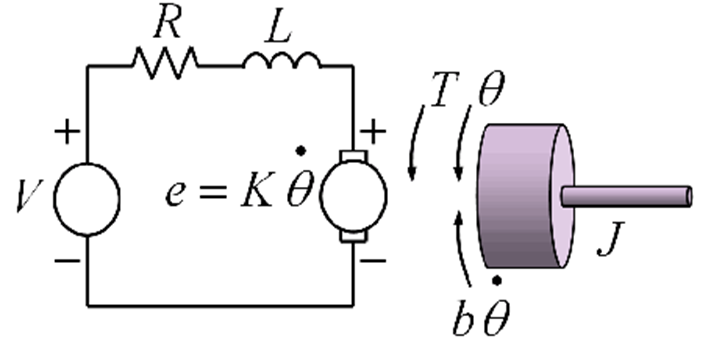
Fig 1 Block diagram of DC motor [5]
This model of DC motor as illustrated by Fig 2 can be represented as a transfer function using the parameters from Table 1, as shown in Equations 1 and 2.


The gyroscope is designed to produce a feedback signal for the stabilization loop by detecting the gimbal’s angular position, enabling the controller to adjust the gimbal to match the input rate command. The specifications for the rate gyro discussed in this research are provided in Table 2 . Based on these specifications, the transfer function of the rate gyro is expressed in the equations 3, and 4 as:
Table 1: Parameter of gimbal system
|
Parameter |
Value |
|
Nominal voltage (V) |
30 V |
|
Armature resistance () |
5 Ω |
|
No load speed |
303 m/sec |
|
Armature inductance () |
4 mH |
|
Moment of inertia of rotor (J) |
0.01 |
|
Motor torque constant () |
0.85 Nm/A |
|
Back EMF constant ( |
0.90 |
|
Natural frequency ( |
50 Hz |
Table 2 : The specifications of the gyroscope sensor
|
Parameter |
Value |
|
Input rate (deg/sec) |
±150 |
|
Scale factor (mV/(deg/sec)) |
100 |
|
bandwidth (Hz) |
400 |
|
Natural frequency (Hz) |
50 |
|
Damping ratio ( |
0.7 |
- Proportional-integral derivative (PID) controller.
- Components of a PID Controller:
Proportional (P): The proportional term produces an output that is directly proportional to the current error value. The controller adjusts the control output based on the magnitude of the error.
Integral (I): The integral term considers the accumulation of past errors. It aims to eliminate steady-state error by integrating the error over time. This helps correct any bias that might cause the system to deviate from the set point.
Derivative (D): The derivative term responds to the rate of change of the error. It helps to predict future error, allowing the controller to take corrective action before the error becomes large [6]
The overall control output is the sum of the three terms:
![]()
where:
u(t) is the control input to the system
e(t) is the error at time t
Kp, Ki, Kd are the proportional, integral, and derivative gains
- Tuning the PID Controller: The performance of a PID controller depends on the values of Kp, Ki, and Kd These parameters must be carefully chosen to achieve the desired performance, so there are three methods for tuning PID controllers include:
- Manual tuning: Adjusting the parameters by trial and error.
- Ziegler-Nichols method: A heuristic method based on system response to oscillations.
- Optimization methods: Techniques like Particle Swarm Optimization (PSO), Genetic Algorithms (GA), or others can be used to find the optimal PID parameters based on performance criteria.
In many cases, modern control systems use PID controllers as a starting point, with more advanced techniques or compensators employed for systems with more complex dynamics.
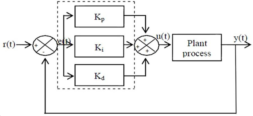
Fig 3: PID controller design
- ZN-PID Controller Design.
The Ziegler-Nichols (ZN) method is a widely used heuristic approach for tuning PID (Proportional-Integral-Derivative) controllers, developed by John G. Ziegler and Nathaniel B. Nichols in the 1940s. This method is particularly beneficial when the mathematical model of the system is not readily available.[7]
The Ziegler-Nichols method is a popular empirical approach for tuning PID controllers (Proportional-Integral-Derivative controllers). It is widely used for determining the optimal PID gains (proportional gain Kp, integral time Ti, and derivative time Td) based on the step response or the closed-loop response of the system.
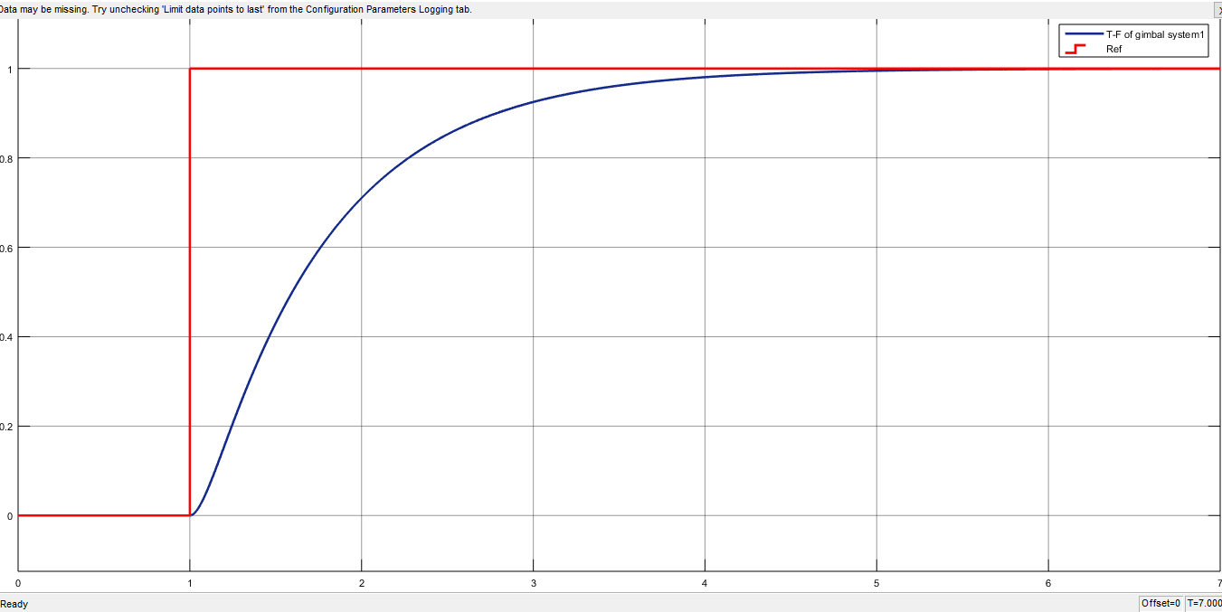
Fig 4: Step response of gimbal system
In the step response method of Ziegler-Nichols as shown in Fig 4, the system will be the open-loop step response to determine the appropriate tuning parameters for the PID controller.
- Obtain the Open-Loop Step Response: Begin by applying a step input to the system (a sudden change, usually between 0-1) and observe the system’s output. Analyze the response to extract some parameters as delay time, steady state value, and time constant based on its characteristics.
- The Parameters for the PID Controller: based on the open-loop step response:
- Proportional gain: Kp=1.2*(T/L)
- Integral time: Ti=2L
- Derivative time: Td=0.5L
So by using the step response of open-loop system, we can extract the parameters such as T=1.21 sec, and L=0.081, then from last equations of Kp, Ti, and Td fine the three gains of PID controller.
Kp= 1.2* (T/L)= 1.2* (1.21/.081)=17.93.
Ti=2L= 2*0.08=0.16 sec, Ki=Kp/Ti= 17.93/0.16=112.10
Td=0.5L=0.5*.08=0.04, Kd=Kp*Td= 17.93*.04=0.717
- Particles swarm optimization.
The Particle Swarm Optimization is defining as (PSO).
PSO is a heuristic optimization algorithm inspired by the social behavior of birds flocking or fish schooling. It’s often used to solve optimization problems where the goal is to find the best solution from a set of possible solutions [8]. PSO is commonly applied in areas such as machine learning, artificial intelligence, and engineering design, the block diagram of PSO algorithm to optimized PID controller of gimbal system as illustrated in Fig.6. And it the steps of how PSO algorithm works:[9]
- Particles: In PSO, each potential solution is represented by a “particle.” These particles move through a multidimensional search space.
- Position and Velocity: Each particle has a position (the solution it’s currently evaluating) and a velocity (the direction and speed at which it will move next).
- Global and Local Bests: Each particle tracks its own best position (local best) and the best position found by the entire swarm (global best).
- Update Rules: At each iteration, particles adjust their positions and velocities based on: Their own best position, the best position found by the swarm, and random factors to introduce diversity into the search.
- Objective Function: The particles evaluate their positions based on an objective function (a function to be minimized or maximized).
- Convergence: Over time, particles are expected to converge toward an optimal or near-optimal solution.
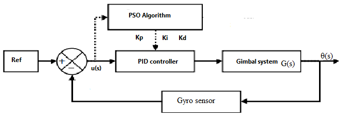
Fig 5 PSO-PID controller of gimbal system
Fig 6 illustrates the flowchart of the Particle Swarm Optimization (PSO) algorithm. The PSO algorithm was implemented using MATLAB code in the form of an m-file, with the program’s code derived from the previous steps and further developed to align with the proposed design, which is employed to effectively tune the PID parameters (Kp, Ki, and Kd). This approach aims to achieve a smooth output for the gimbal system while minimizing Integral Squared Error (ISE, ITAE), overshoot, and settling time, in comparison to traditional methods such as Ziegler-Nichols (ZN).
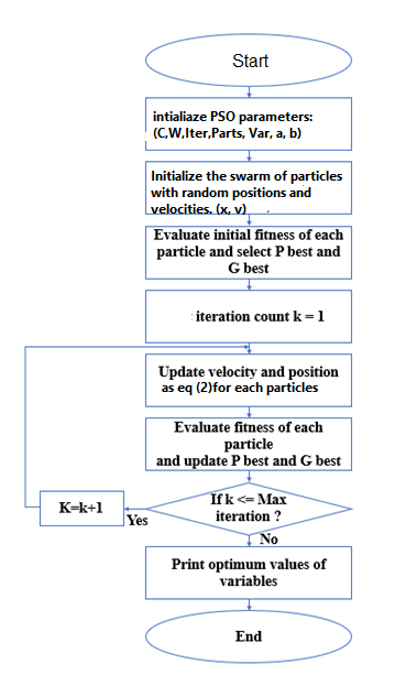
Fig 6 PSO flowchart
- Simulation results.
In this paper, the gimbal system was controlled using two distinct approaches. The first method, a traditional approach, employed the Ziegler-Nichols method for PID controller tuning to obtain the step response, as well as to compute the Integral of Time-weighted Absolute Error (ITAE) and Integral of Squared Error (ISE). These results were then compared with those obtained from the second method, which applied a novel artificial intelligence technique, namely the Particle Swarm Optimization (PSO) method.
- System response using the Ziegler-Nichols PID controller.
A ZN tuned PID controller was implemented to control the gimbal system, where Fig 7 illustrates the system’s control model.
In the simulation results with our consideration of an initial angle of gimbal system is 1 rad, we have obtained acceptable results as shown in below Fig 8, the settling time is 1.76 sec, the overshoot is 55%, the integral time absolute error (ITAE) is 0.2055, and the integral square error (ISE) is 0.08921.
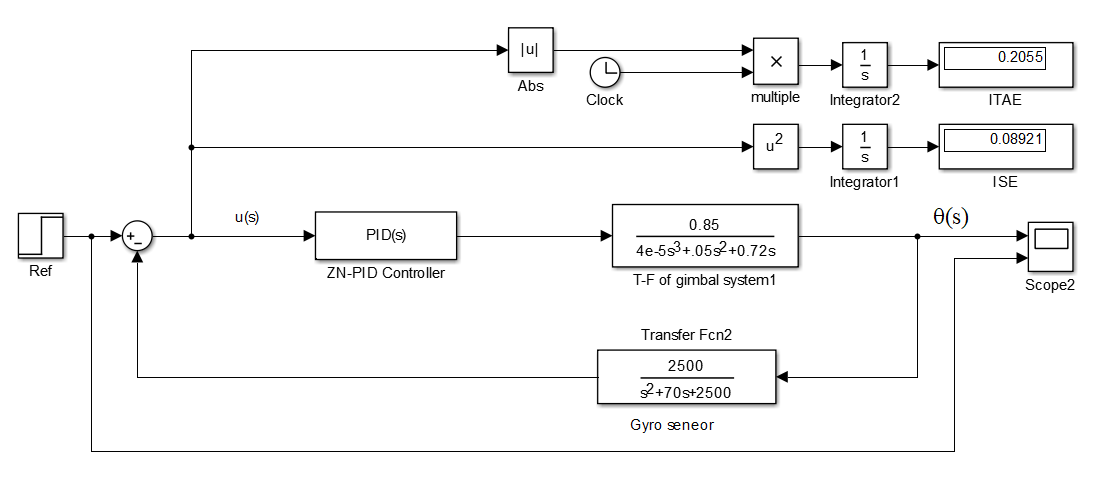
Fig 7 Gimbal system with ZN-PID
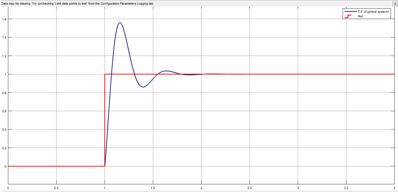
Fig 8 The ZN- PID angle response
- System response using the PSO-PID controller.
To optimize the PID controller gain parameters for smooth system control, it is essential to finely tune the parameters Kp, Ki, and Kd. In recent years, several advanced techniques have been developed for this purpose.
In this paper, the Particle Swarm Optimization (PSO) algorithm is applied, and the MATLAB code (m-file) has been carefully developed to appropriate our design which illustrate the optimized PID with PSO by Fig 9. The chosen PSO parameters are as follows: the number of particles in the swarm is 100, the maximum number of iterations is 120, the acceleration coefficients (C1 and C2) are set to 2, the inertia weight (W) is 0.9, and the upper and lower bounds for the PID gains (Kp, Ki, and Kd) are in the range of 0 to 120.
And to Initialize particle positions and velocities of particles as:
positions = lower_bound + (upper_bound – lower_bound)* rand(particles, 3)
velocities = rand (particles, 3).
For all the number of iterations for a numbers of particles and updating its positions and velocities, the optimized parameters of PID are Kp=10.4, Ki=0.0, and Kd=0.80.
As shown in Fig. 10, the optimized PID angle response using the PSO algorithm demonstrates zero overshoot, which is crucial for many applications. The rise time is 0.093 seconds, the settling time is 0.281 seconds, the ITAE is 0.0862, and the ISE is 0.05602. These results are deemed acceptable and satisfactory for our design.
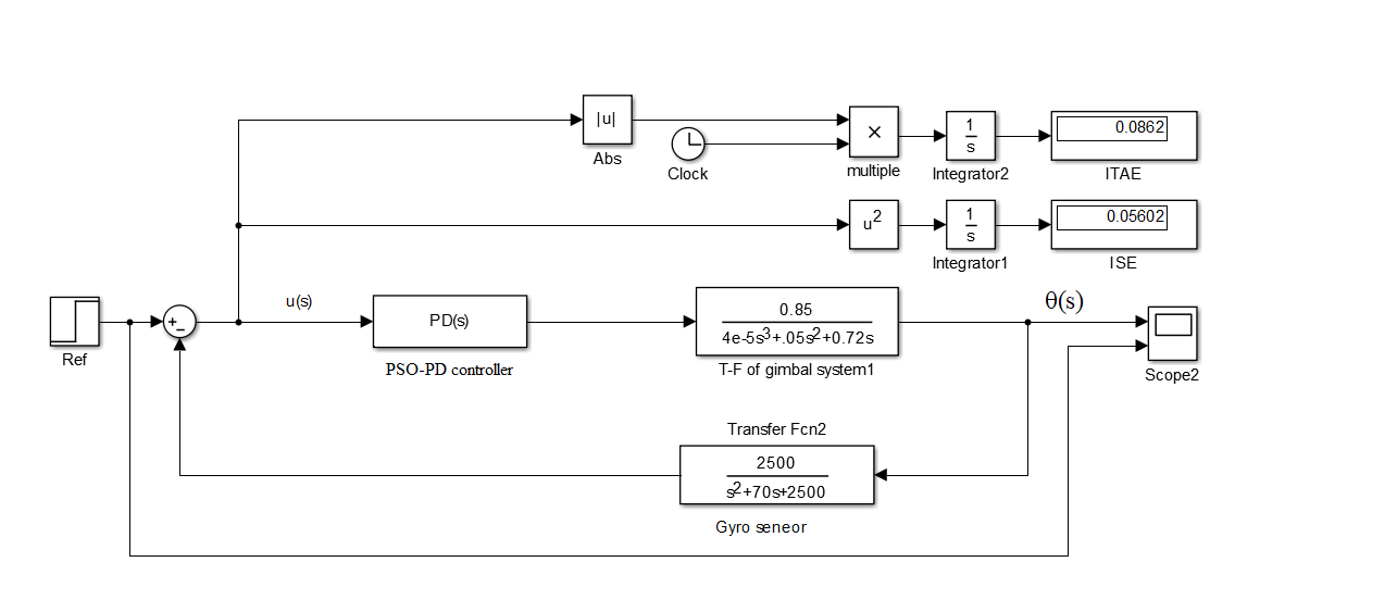
Fig 9 Gimbal system with optimized PID with PSO
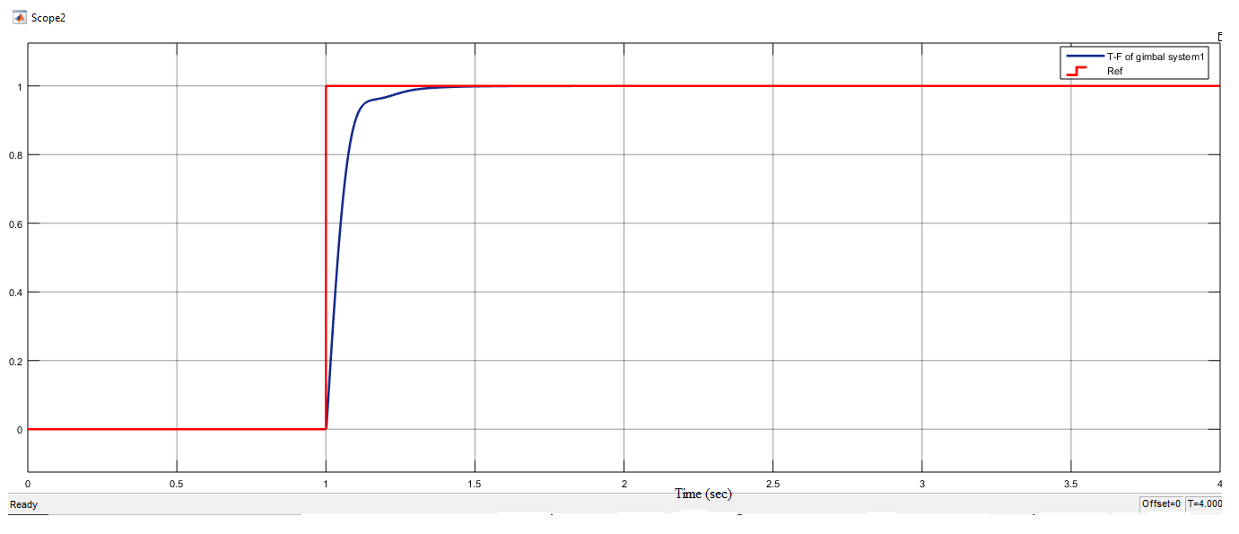
Fig 10 The optimized PID angle response using the PSO algorithm
- Conclusion
In this research, precise control of a gimbal system is essential to maintain stability despite external disturbances or motions. PID controllers are typically used to ensure the gimbal’s desired orientation by adjusting actuators based on sensor feedback. The PID controller was optimized using the PSO algorithm, with tuning performed in Simulink MATLAB. The optimal results were obtained with PID parameters Kp=10.4, Ki=0.0, and Kd=0.80, which minimized the Integral of Squared Error (ISE) to 0.05602 and eliminated overshoot, while achieving a very short settling time of 0.281 seconds. This intelligent algorithm significantly enhances the PID controller’s performance, making it smarter and more effective for a wide range of industrial applications.
References.
- Kennedy, James, and Russell Eberhart. “Particle swarm optimization.” Proceedings of ICNN’95-international conference on neural networks. Vol. 4. IEEE, 1995.
- Wang, Dongyun, and Guan Wang. “Parameters optimization of fuzzy controller based on improved particle swarm optimization.” 2008 International Conference on Intelligent Information Hiding and Multimedia Signal Processing. IEEE, 2008.
- I. S. Okoro and C. O. Enwerem, “Robust control of a DC motor,” Heliyon, vol. 6, no. 12, 2020, https://doi.org/10.1016/j.heliyon.2020.e05777.
- A. S. Kori, C. M. Ananda and T. S. Chandar, “Robust control of single axis gimbal platform for micro air vehicles based on uncertainty and disturbance estimation,” 2016 7th International Conference on Mechanical and Aerospace Engineering (ICMAE), 2016.
- Abd Alati M. Ahmed, ‘’ optimization of hybrid fuzzy- proportional derivative controller using PSO for single axis gimbal system ‘’ MSc thesis, 2022, university technology Malaysia (UTM).
- Jitendra Sharma, Yogesh V. Hote, Rajendra Prasad, Robust PID Control of Single-axis Gimbal Actuator via Stability Boundary Locus,IFAC-PapersOnLine,Volume 53, Issue 1,2020.
- Eka Suci Rahayu , Alfian Ma’arif , Abdullah Cakan ‘’ particles swarm optimization (PSO) tuning of PID control on DC motor ‘’ Vol. 2, No. 2, 2022, pp. 435-447 ISSN 2775-2658.
- R. Caponetto and M. G. Xibilia, “Fractional order PI control of a gimbal platform,” 2017 European Conference on Circuit Theory and Design (ECCTD), 2017, pp. 1-4, doi: 10.1109/ECCTD.2017.8093271.
- Simi Simon, P . Rajalakshmy, 2014, Speed Control of DC Motor using PSO based Fuzzy Logic Controller, INTERNATIONAL JOURNAL OF ENGINEERING RESEARCH & TECHNOLOGY (IJERT) Volume 03, Issue 02 (February 2014).
- Ghareaghaji, Ali. (2015). A Comparison between Fuzzy-PSO Controller and PID-PSO Controller for Controlling a DC Motor. Bulletin of Electrical Engineering and Informatics. 4. 10.11591/eei.v4i2.328.

